Shortest Path Bridging Part 2 - Setting up the backbone
Before enjoying all things SPB, we have to setup the backbone mesh of SPB-enabled switches/routers. In this setup, Alcatel-Lucent Omniswitch 6900s will be used. Check them out here. They are plucky little things that have an amazing set of features, a very competetive price, and no weird licensing schemes!
The AOS syntax will be somewhat confusing if you are a Cisco/Juniper person. In fact, it will be confusing no matter what router-lingo you are used to. Deal with it. You are smart. AOS is flat as a pancake - No levels, no hierarchy. Nothing you can “enter”, with the exception of a vrf. You can go into a vrf. And stay there for as long as you want to. No “conf t” or “edit”, or “commit” - If you type it in, it is there and online (some things have to be enabled after creation though.).
This isn’t really meant to be a comprehensive guide to how the AOS cli works, only to how you get SPB up and running. With that said, the configuration will look very much alike in an Extreme switch, albeit with their lingo.
Let’s get on with it.
BVLAN
A BVLAN, or “backbone VLAN” only has a special meaning for a SPB-node. For any other non-SPB switch in the path, it is just a VLAN. Ok, a VLAN that needs a slightly bigger frame-size (1524). Other than that - There’s nothing more to it. Just switch it and think of something else.
If you are a SPB-enabled node, one BVLAN will carry the control traffic. The same BVLAN can also carry services. One has to remember that a BVLAN represents a topology. The control BVLAN will carry the shortest path forwarding trees, created by all participating SPB nodes. Each node have their own SPF topology of the SPB mesh. And if you only have ONE topology, there is not much need for more than one BVLAN.
It is very easy to think that a BVLAN can be used as an administrative segmentation - Like, one BVLAN for server-services, one for user-services etc. Don’t fall into that trap! Every BVLAN adds a significant amount of controller traffic. If you have hundreds of SPB nodes, carrying thousands of services over many SPF topologies (BVLANS), you might be in trouble. Don’t get me wrong - IS-IS scales very well as a protocol. Hence - SPB does to, but only if you set it up properly. A thousand SPB nodes in the same network isn’t impossible. There are networks running today that have more nodes than that, without any issues.
Some operational things to be aware of:
-
When adding a path for SPB through a legacy environment, i.e: spanning the BVLAN through legacy switches - think of it as adding another point-to-point link to the SPB underlay. A VLAN stretched via legacy switches in order to connect two SPB-nodes. The legacy environment switches will be invisible to the SPB control plane, it will only see the SPB nodes. SPB links are normally point-to-point, since IS-IS is a link-layer protocol. An SPB node anticipates to see one neighbor per link. You can use a shared ethernet segment for connecting SPB nodes, but that requires a bit more configuration. Be aware of this. SPB needs to know if it should expect more then one node via one link.
-
If using more then one link between two SPB nodes - Create a linkagg first, and enable SPB over it to use the extra bandwidth properly. If you don’t create a linkagg, the switches will decide which way to use based on the highest node-id instead. This is the tie-breaker when having multiple direct connections to another node. It will work right out of the box, and it will never create any loop, but it will work in a more spanning-tree-like way. Only one path will be used at a time. If the chosen primary link goes down, the secondary will be used, with the same failover time as any other link. If you want all links to be used in this scenario, use linkaggs.
In an ALE switch (Alcatel-Lucent Enterprise), VLANs 4000-4016 are reserved for BVLAN use, but you can actually use whatever VLAN-id you want to. The only thing with VLANs 4000-4016 is that they can’t be used for anything else than being BVLANs - in an ALE switch that is.
All deployment guides tells you to never use more than four BVLANs at the same time in the same SPB-network. As stated earlier - If you have ONE topology, there is no need for many BVLANs. And with one topology, you only need one BVLAN for the services AND the controller traffic. Enough about that. Let’s build the backbone!
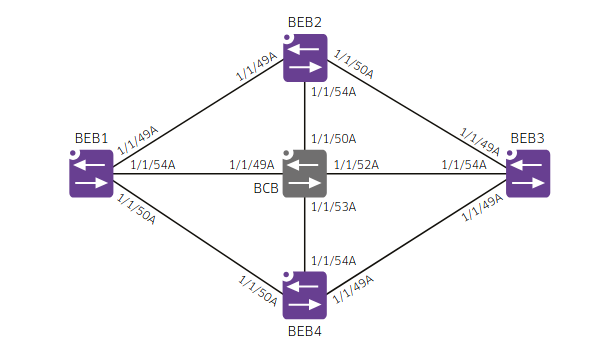
In this little setup of SPB, we have five participating nodes, all directly connected with several 100G interfaces each. And to refresh the abbreviations: BEB = Backbone Edge Bridge. This is an SPB-node that deliver services to someone/something. A BEB is simply put a SPB-node that has customer-facing ports.
BCB = Backbone Core Bridge. This is a SPB-node that hasn’t got any services enabled on any ports. It just switches the BVLANs, and doesn’t know nor care about any services within the BVLAN.
BEB1-> spb bvlan 4000-4001
BEB1-> spb isis control-bvlan 4000
BEB1-> spb isis interface port 1/1/49A
BEB1-> spb isis interface port 1/1/50A
BEB1-> spb isis interface port 1/1/54A
BEB1-> spb isis admin-state enable
The config will be the same for ALL the five nodes, with the exception of BCB1, which uses one interface more than the rest, since it is in the middle of the mesh. Other than that, the backbone config is identical, and pretty self-explanatory. Setting VLAN 4000-4001 as BVLANs automatically disables STP on them. AOS assigns a unique ECT-ID (Equal-cost-tree) to each BVLAN for maximizing the chance that different BVLANs will create different shortest path trees.
The SPB-nodes will exchange ISIS “Hello” messages over the control BVLAN 4000, and form point-to-point adjacencies. LSPs are exchanged, a topology database is created, and one SPT is built for each BVLAN. It would also be possible to set the same backbone up via a legacy switch network that has trunk-ports with VLAN 4000-4001 connected to the SPB-nodes, effectively creating the backbone transparently via the old network. Anyway, that’s it. Your backbone is up and ready!
Caveats with different link speeds
One thing to remember here is that SPB doesn’t have any way of determining the capacity of the links by itself. If you have the same link capacity in all directions as in the above example, this doesn’t matter. BUT… If you have a few links on 100G, a few on 40G, maybe some 25G, and a bunch of 10G links, you NEED to configure the link metric properly.
Failing to set this correctly CAN result in packet loss.
Default link metric is 10 on all links. Since all links are open and can/will be used, you need to provide this information to the control plane so that SPB never over-saturate a link. Set the link metric so that it is a factor of the link capacity, where your highest link capacity has the lowest value, for example:
400G links with metric 250
100G links with metric 1000
40G  links with metric 2500
25G  links with metric 4000
10G  links with metric 10000
This additional info makes sure that the control plane always can do proper loadbalancing over the links without saturating them. ECMP comes into play when there are several paths with the same length between a source and a destination, this will work even if the paths include a 10G and a 100G interface due to this added information.
With the added correct link metric, you will always get a properly weighted ECMP traffic distribution.
Now, it is time to setup a few services on our new shiny backbone.